Cyclist
A RISC-V Single Cycle Processor in Verilog
This is the course project of Computer Systems I, the first course in a trilogy on computer systems. The first part deals with digital logic and computer organization, while the second and third will include operating system and computer architecture respectively.
Since a single cycle processor executes one instruction in each cycle, just like riding a bicycle, I named it Cyclist. It implements the instructions colored green in the following picture from RV32I Base Instruction Set, RISC-V ISA:
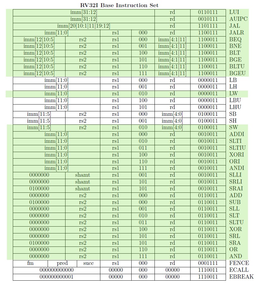
The following is a brief summary of the design and test process, which may be helpful to you if you are working on a similar project. This processor will be improved to a pipelined processor with more instructions supported in the following semester, but that will appear in another project page when completed.
Design
I examined the instruction table along with the RISC-V specification and divided the instructions into 10 types, summarized in the following table:
| Type | Instructions |
|---|---|
| U(lui) | LUI |
| U(auipc) | AUIPC |
| J | JAL |
| I(jalr) | JALR |
| B | BEQ,BNE,BLT,BGE,BLTU,BGEU |
| I(load) | LW |
| S | SW |
| I(a/l) | ADDI,SLTI,SLTIU,XORI,ORI,ANDI |
| I(a/l)spe | SLLI,SRLI,SRAI |
| R | ADD,SUB,SLL,SLT,SLTU,XOR,SRL,SRA,OR,AND |
Careful examination of each type of instructions yields the following datapath and control signal design.

| Inst Type | ImmType | ALUop | ALUSrc | WriteBackSrc | PCSrc | RegWrite | MemWrite |
|---|---|---|---|---|---|---|---|
| R | R | R | rs2 | ALU | PC4 | Enable | Disable |
| I(load) | Iord | IloadS | imm | DataMem | PC4 | Enable | Disable |
| I(a/l)ord | Iord | Ial | imm | ALU | PC4 | Enable | Disable |
| I(a/l)spe | Ispe | Ial | imm | ALU | PC4 | Enable | Disable |
| S | S | IloadS | imm | - | PC4 | Disable | Enable |
| B | B | B | rs2 | - | BSuccess | Disable | Disable |
| J | J | J | - | PC4 | PCimm | Enable | Disable |
| U(lui) | U | U | - | imm | PC4 | Enable | Disable |
| U(auipc) | U | U | - | PCimm | PC4 | Enable | Disable |
| I(jalr) | Iord | Ijalr | imm | PC4 | ALU | Enable | Disable |
Encode these into Verilog, we have got a processor! Simple, right?
Test
I made this testing asm and converted it to a coe file using a Python script. The coe file initializes the instruction memory, from which machine instructions will be fechted. The assembly is designed in such a way that if something goes wrong, the processor will get stuck in an infinite loop.
After fixing some bugs, it run through the end in simulation and works just well on board. Test success!
Run some C Code
The moment I finished the test, I realized that I can actually run C code on my just designed processor. The process is simple.
- Write a main function, do some operations and give the result as the return value.
- Use
riscv32-unknown-elf-gccto compile it into relocatable file (.ofile). - Use
readelfto extract the encodedmainfunction. - format it into a
coefile, push it to Vivado and download it to the board.
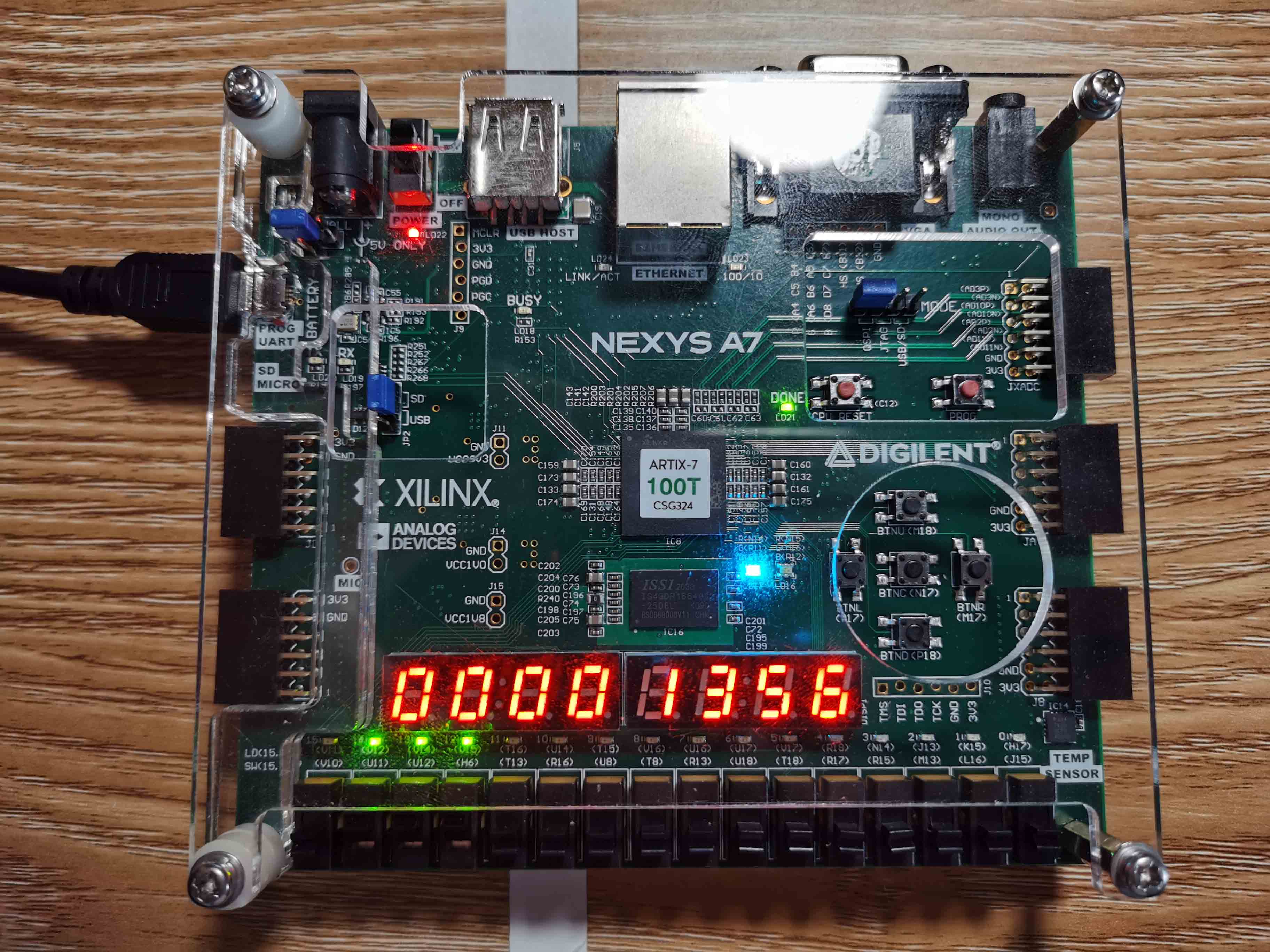
Here is an example that add from 0 to 99. The code is
and the result is 4950 = 0x1356, as the board output says: